Mooring System Generation & Load Analysis
Celtic Sea Floating Offshore Wind – Mooring System Generation & Load Analysis
Executive Summary
This study establishes the mooring physics layer of Morie Analytics by transforming floating wind layouts into physically consistent mooring systems and preliminary design load outputs.
Using previous data and simulation tools, the workflow generates mooring systems and extracts mudline-level loads for engineering assessment that will be transferred into padeye-level loads in the following study case (morie_anchor).
The result is a reproducible computational pipeline that connects geometry, quasi-static equilibrium physics and frequency-domain dynamic response.
This module represents the first stage where physical system behavior governs design outcomes, transitioning from geometry to force-driven engineering.
Site intelligence → Layout generation → Soil reconstruction → Mooring physics → Anchor verification → Cable optimization
Project Scope
- Mooring system generation
- Shared-anchor configurations
- Environmental design load cases evaluation
- Dynamic response analysis
This study converts layout geometry into design-driving loads.
Engineering Context
Floating wind farms increasingly adopt shared-anchor configurations, introducing coupled load interaction.
Accurate design requires:
- Geometry and pretension
- Static equilibrium
- Directional loading
- Dynamic response
This workflow provides a continuous mechanical link from layout to anchor demand.
Inputs and Data Sources
This study builds directly on upstream Morie Analytics outputs:
From morie_site
- Bathymetry and soil classification grids
- Lease boundary definitions
From morie_layout
- Selected floater cluster
- FOWT coordinates
- Shared-anchor typologies and coordinates
Additional Inputs
- Farm model configuration
- Mooring line properties
- Environmental design load cases for representative extreme conditions in the Celtic Sea
All inputs are integrated into a simulation-ready framework.
This provides the mechanical inputs required for load generation.
System Flow
Layout → Mooring Definition → Equilibrium → Dynamic Response → Load Extraction
The architecture ensures traceability from geometry to load outputs.
Processing Workflow
- Load farm configuration
- Generate mooring geometry
- Detect and merge shared anchors
- Adjust line lengths and pretension
- Solve static equilibrium
- Evaluate environmental response
- Identify governing load case
- Reconstruct time-domain response
- Extract mudline loads
- Aggregate anchor demand
This converts system geometry into design-driving loads.
Design Basis
The study is presented as a preliminary engineering workflow intended for concept-level and early-stage floating offshore wind assessment.
The objective is to generate physically consistent mooring configurations and representative load pathways suitable for downstream anchor and system evaluation.
The current implementation focuses on:
- Characteristic environmental loading conditions
- Preliminary Ultimate Limit State (ULS)-type assessment
- Frequency-domain dynamic response
- Shared-anchor load interaction
The workflow does not currently represent a fully code-qualified mooring design process.
The following aspects remain outside the present scope:
- Partial safety factor application
- Detailed fatigue verification
- Fully coupled nonlinear time-domain dynamics
- Second-order low-frequency response effects
- Installation and operational load cases
These aspects would require integration with higher-fidelity design workflows and project-specific certification criteria.
Mooring System Definition
Mooring systems are generated from floater layouts using deterministic geometric rules that define line topology and load transfer paths.
Key Assumptions
- 3 mooring lines per floater
- 120° angular spacing
- Fixed anchor radius
- Global coordinate consistency
The reference heading of each mooring system is assigned deterministically relative to the global layout orientation in order to preserve consistent shared-anchor topology generation across the farm.
Sensitivity to alternative heading assignments is recognized as an important downstream engineering consideration.
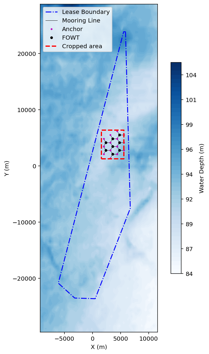
Figure 1 – Mooring system geometry showing floater positions, line headings, and anchor locations.
Engineering Significance
This deterministic geometry ensures:
- Reproducibility across layouts
- Compatibility with shared-anchor configurations
- Consistent load transfer paths
Shared Anchor Topology
Coincident anchor locations are merged to define shared-anchor nodes, creating a connected load network.
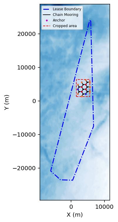
Figure 2 – Shared-anchor configurations showing multiple line connections per anchor.
The shared-anchor network can then be placed back into its full seabed context, integrating bathymetry, soil conditions and spatial load-transfer geometry.
This transforms the system from a purely topological representation into a site-dependent mechanical model.
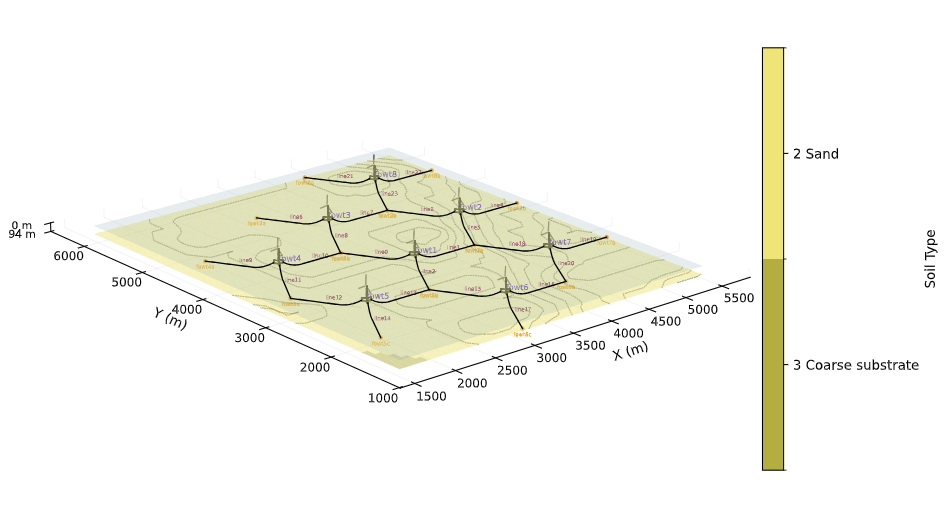
Figure 3 – Integrated mooring system showing layout geometry, shared-anchor topology, bathymetry and soil classification.
Engineering Significance
Shared anchors enable:
- Reduction in anchor count
- Compact layouts
- Cost-efficient seabed usage
But require:
- Accurate load aggregation
- Directional load resolution
- Consistent transformation into anchor demand
Pretension & Equilibrium
The mooring system is solved for the quasi-static equilibrium, establishing the baseline mechanical state.
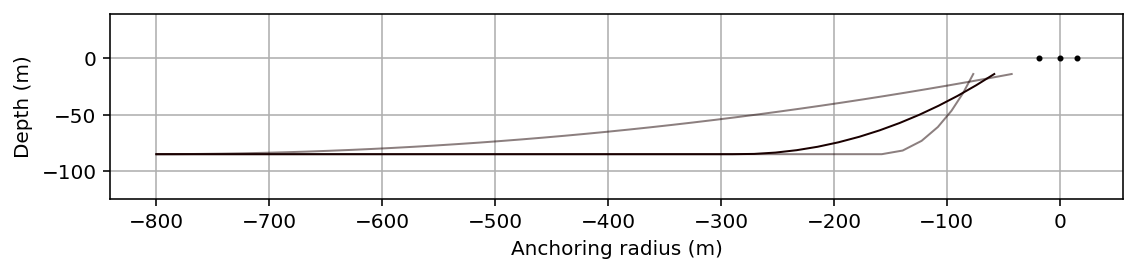
Figure 4 – Mooring line catenary profile.
Engineering Interpretation
The equilibrium configuration defines:
- Baseline load distribution across lines
- Dominant horizontal force components driving anchor demand
- Influence of line geometry on load direction
Pretension governs:
- System stiffness
- Load sharing between lines
- Sensitivity to environmental forcing
Environmental & Dynamic Response
RAFT is used here as a frequency-domain preliminary response tool suitable for early-stage system assessment.
The present workflow primarily captures first-order hydrodynamic response and does not fully represent nonlinear low-frequency slow-drift effects or fully coupled time-domain dynamics, which may become significant in detailed mooring verification studies.
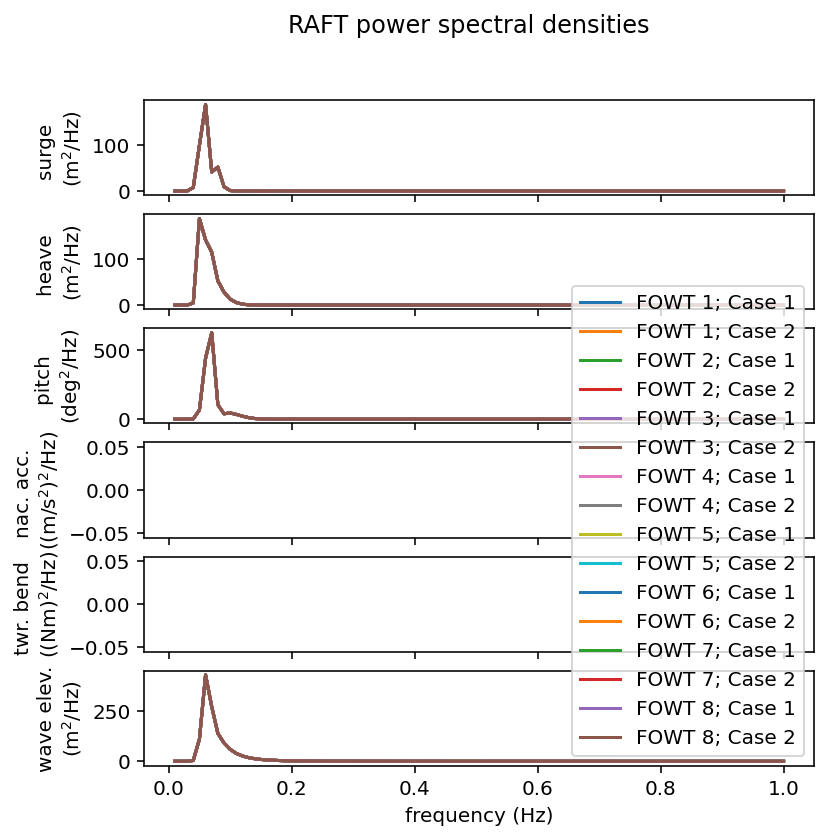
Figure 5 – Environmental load cases and frequency-domain response.
Engineering Interpretation
Dynamic loading introduces:
- Direction-dependent load redistribution
- Oscillatory tension behavior
- Frequency-dependent amplification
This reveals how environmental conditions translate into load variability and extremes.
Critical Load Case Identification
The governing load case is selected based on maximum tension response across all conditions. In this case, the maximum load for an omni-directional environmental loading happens for the upwind direction.
Engineering Interpretation
Critical conditions typically arise when:
- Wave direction aligns with mooring lines
- Load concentration occurs in windward lines
- Dynamic amplification peaks
This defines the design-driving scenario for anchor verification.
Time-Domain Reconstruction
Time series are reconstructed from Power Spectral Density (PSD) outputs to evaluate extreme response characteristics and preliminary fatigue-related load variability.
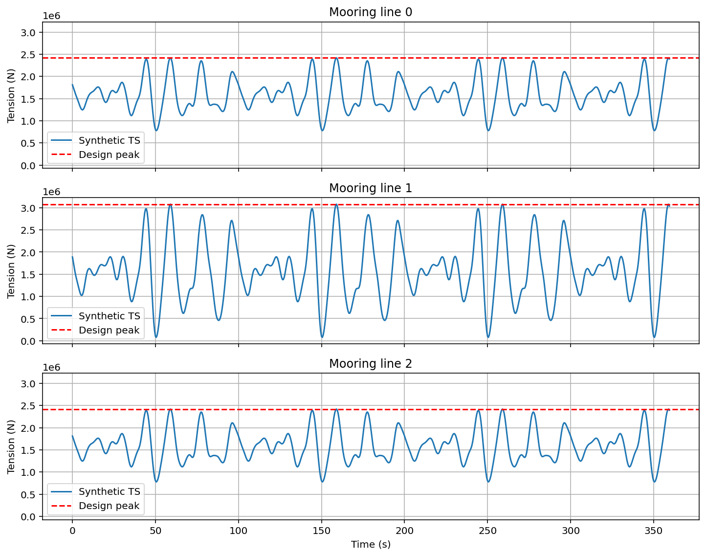
Figure 6 – Time-domain reconstruction of mooring line tension.
Engineering Significance
This enables:
- Extreme load identification
- Preliminary fatigue response characterization
- Validation of dynamic response
Outputs Generated
Mooring-Level Outputs
- Mooring geometry and topology
- Equilibrium configuration
- Line tensions and profiles
- Mudline loads (Hm, Vm, θm)
Loads are extracted at the mudline elevation point that is assumed as a fixed point in the seabed.
Dynamic Outputs
- Frequency-domain response
- PSD characterization
- Critical load case
- Time-domain tension histories
Anchor-Level Outputs
- Resultant loads (Hm, Vm, θm)
- Load contribution per line
Engineering Applications
- Mooring system optimization
- Environmental sensitivity studies
- Offset sensitivity analysis for dynamic cable coupling
- Preliminary fatigue-related response assessment
This enables:
Mooring Behavior → Anchor Demand → Engineering Assessment
Relationship to Other Morie Study Cases
This study is the mechanical response layer of the Morie Analytics workflow.
Receives from
- morie_site → bathymetry context
- morie_layout → geometry and topology
- morie_soil → soil properties at anchor locations
Feeds into
- morie_anchor → soil-dependent load transfer and capacity verification
- morie_cable → system configuration constraints
It provides the mechanical transition from system geometry to design-driving loads.
Why It Matters Commercially
This workflow enables:
- Preliminary design of the mooring lines
- Validation of shared-anchor strategies
- Direct linkage between layout decisions and load consequences
- Improved CAPEX control through load-driven design
This is the stage where:
- Layout decisions become load consequences
- Shared-anchor strategies can be comparatively assessed
- System configuration directly impacts cost
Aspects to Improve
- Probabilistic design load cases analysis
- Automated optimization loops
- Soil–mooring interaction coupling
- Nonlinear seabed contact models
- Integration with installation constraints
Design Philosophy
This study reflects the Morie Analytics approach:
- Physics-informed
- Modular
- Traceable
- Engineering-focused
- Scalable