Dynamic Cable Design & Configuration Optimization
Celtic Sea Floating Offshore Wind – Dynamic Cable Design & Configuration Optimization
Executive Summary
This study establishes the system closure layer of Morie Analytics by transforming system behavior into optimized dynamic cable configurations.
Building on upstream modules, the workflow integrates bathymetry, mooring offsets and hydrodynamic response to design constraint-compliant dynamic cables. The result is a constraint-driven optimization framework producing mechanically feasible cable configurations.
This module represents the final stage of Morie’s building blocks where system behavior is translated into preliminary cable configuration assessment.
Site intelligence → Layout generation → Soil reconstruction → Mooring physics → Anchor verification → Cable optimization
In floating offshore wind, the dynamic cable is where the entire system converges: the interface between the moving floating structure, the seabed infrastructure and the electrical network itself.
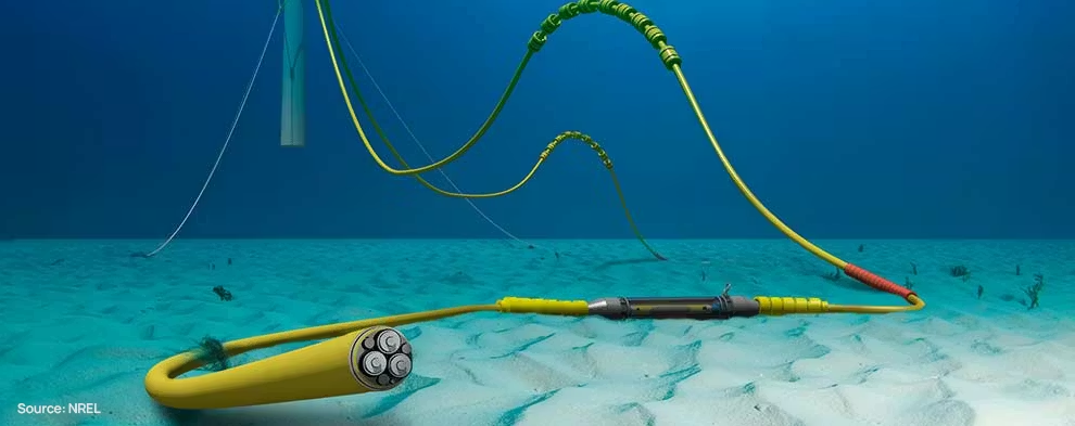
Figure 1 – Dynamic power cable as the interface between the floating system and the subsea electrical network - source: NREL.
Project Scope
- Dynamic cable configuration modeling
- Mooring offset integration
- Hydrodynamic motion input
- Constraint-based optimization
- Geometry and performance evaluation
This study converts system behavior into optimized cable configuration.
Engineering Context
Dynamic cables must accommodate:
- Floater motion
- Environmental cyclic loading
- Seabed interaction
- Strict mechanical and geometrical constraints
Cable design is a constraint-dominated problem, balancing:
- Geometry
- Curvature
- Tension
- Seabed contact
This workflow ensures cable design reflects representative system response.At this stage, coupling between floater motion and cable response is represented through transferred motion envelopes and boundary conditions rather than through fully coupled nonlinear time-domain simulation.
Inputs and Data Sources
This study builds directly on upstream Morie Analytics outputs:
From morie_site
- Bathymetry and soil classification grids
- Lease boundary definitions
From morie_layout
- Floater geometry
- Fairlead position
From morie_mooring
- Platform offset
Additional Inputs
- Model configuration
- Dynamic motion response
- Cable properties and constraints
This provides the boundary conditions for cable design optimization.
System Flow
Bathymetry → Motion → Cable Geometry → Constraint Evaluation → Optimization
The architecture ensures consistent coupling between system behavior and cable design.
Processing Workflow
- Load configuration
- Extract bathymetry
- Define fairlead geometry
- Compute mooring offset
- Extract motion response
- Define cable model
- Apply constraints
- Run optimization
- Evaluate final configuration
This converts system response into optimized cable configuration.
Design Basis
This workflow is intended as a preliminary dynamic cable assessment framework suitable for early-stage floating offshore wind studies.
The current implementation focuses on:
- Motion-envelope-driven cable configuration
- Geometric and mechanical constraint evaluation
- Preliminary configuration optimization
- System-level coupling with floater response
The workflow does not currently include:
- Full-array routing optimization
- Electrical power-flow optimization
- Detailed fatigue verification
- Vortex-Induced Vibration (VIV) assessment
- Fully coupled nonlinear cable dynamics
- Installation engineering analysis
Cable System Definition
The cable is modeled as a multi-segment system connecting:
- Seabed touchdown point or range
- Suspended buoyant sections
- Floater fairlead position
The configuration must remain within a defined geometric envelope, including:
- Maximum and minimum hog heights (upper excursion limits)
- Maximum and minimum sag depths (lower excursion limits)
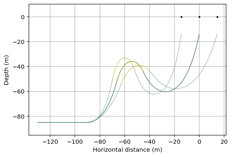
Figure 2 – Initial cable configuration.
Engineering Interpretation
These limits define the allowable vertical excursion of the cable, ensuring:
- Controlled curvature along suspended sections
- Acceptable clearance from the seabed and water surface
- Compatibility with floater motion and environmental loading
They act as primary geometric constraints, governing feasible cable configurations under the full system motion envelope.
System Motion Envelope
The cable boundary conditions are defined by the combined effect of:
- Quasi-static offset from mooring equilibrium
- Dynamic motion induced by environmental loading
Together, these define a motion envelope describing the full spatial excursion of the floater.
Engineering Interpretation
- Sets the kinematic boundary condition for cable design
- Defines maximum horizontal excursion and dynamic amplification
- Directly governs cable span, curvature and touchdown behavior
Cable Design Model
The cable system is modeled as a multi-segment structure responding to:
- Self-weight and buoyancy distribution
- Seabed interaction at touchdown
- Floater motion envelope
- Hydrodynamic excitation
Engineering Interpretation
Cable behavior emerges from the interaction between:
- Geometry (segment lengths and buoyancy)
- Boundary conditions (motion envelope)
- Constraint limits (tension, curvature, seabed contact)
The problem is inherently geometry-driven under dynamic constraints, where feasible configurations must adapt to system motion while remaining within allowable limits.
Optimization Problem
Design Variables
- Segment lengths
- Buoyancy distribution
- Lay lengths
Constraints
- Minimum lay length
- Maximum sag and hog heights
- Curvature limits
- Tension safety factors
- Touchdown range limits
Objective
The optimization seeks a configuration that:
- Minimizes a simplified configuration cost function based on cable length, buoyancy distribution and geometric efficiency
- Satisfies all mechanical and geometric constraints
- Remains robust under the full motion envelope
This results in a feasible and constraint-compliant cable configuration, rather than an idealized solution.
Optimization Convergence
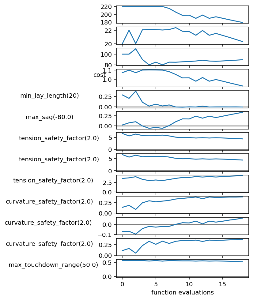
Figure 3 – Optimization convergence.
Engineering Interpretation
The optimization balances:
- Feasibility (constraint satisfaction)
- Efficiency (cost reduction)
Optimized Configuration
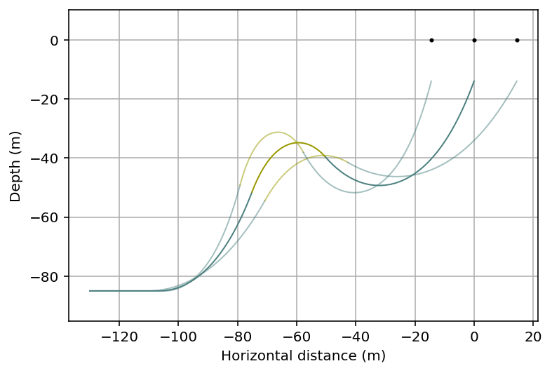
Figure 4 – Optimized cable configuration.
Outputs Generated
- Optimized cable geometry
- Constraint verification
- Tension and curvature profiles
- Sag, hog and touchdown positions
- Optimization history
Engineering Applications
The outputs support:
- Dynamic cable design
- Constraint-driven optimization
- System-level coupling
- Early-stage engineering decisions
This enables:
System Motion → Cable Geometry → Constraint-Compliant Design
Relationship to Other Morie Study Cases
This study is the system closure layer of the Morie Analytics workflow.
Receives from
- morie_site → bathymetry context
- morie_layout → geometry and topology
- morie_mooring → static and dynamic offsets
- morie_anchor → validated system constraints
Completes
The cable branch of the system workflow.
It provides the final transition from system behavior to mechanically feasible cable configuration design.
Why It Matters Commercially
Dynamic cables are among the most critical and costly components of floating wind systems.
- Reduces overdesign
- Ensures constraint compliance
- Balances cost and reliability
- Supports early-stage decision making
This is where:
- System behavior meets mechanically feasible cable configuration design
- Constraints define feasibility
- Preliminary cable design decisions are assessed
Aspects to Improve
- Fatigue and Vortex Induced Vibrations (VIV) analysis
- Probabilistic motion study
- Touchdown cable rug abrasion mitigation strategies
Design Philosophy
This study reflects the Morie Analytics approach:
- Physics-informed
- Modular
- Traceable
- Engineering-focused
- Scalable